


What should we do if the amplifier cannot be turned on?
Views : 45433
Update time : 2019-05-11 10:51:29
 Why is the amplifier unable to turn on?
When the amplifier cannot be turned on, it is possible that there is a problem with the components inside the amplifier. Fuses, IGBT transistors, bridge rectifiers, transistors 130-06 may be problematic.
Why are these parts damaged?
Mainly due to the unstable voltage of the connected power amplifier or the overload of the power amplifier.
How to solve this problem?
First, you need to prepare some tools.
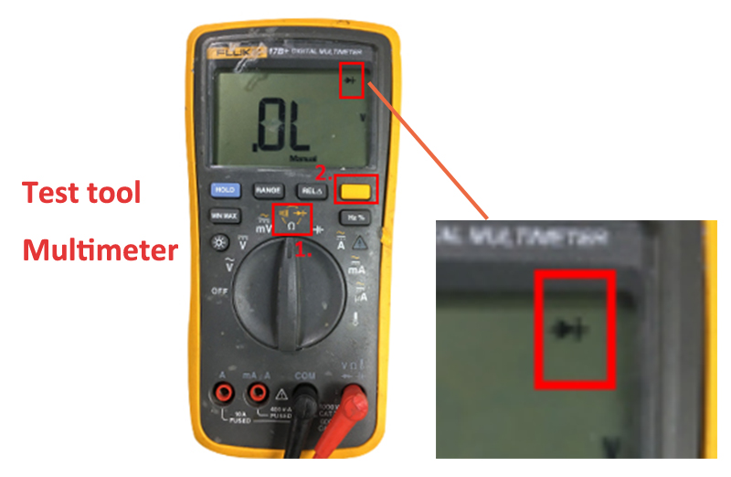
1.Testing tool: Multimeter
Select your multimeter to Diode grade.
(Remark:Maybe your multimeter different from below picture,but just adjust it until show the Diode grade mark )
 You need to pay attention to a problem before we test:To avoid short circuit, if you have turned on your amplifier, please wait 20minute before your Testing! Because there is some electricity still stay in the power supply. They should be released in 15-20mins at least.
Now let's start testing.
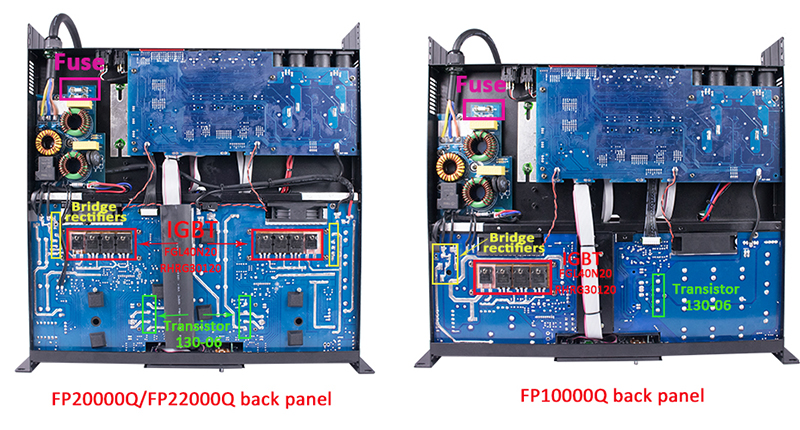
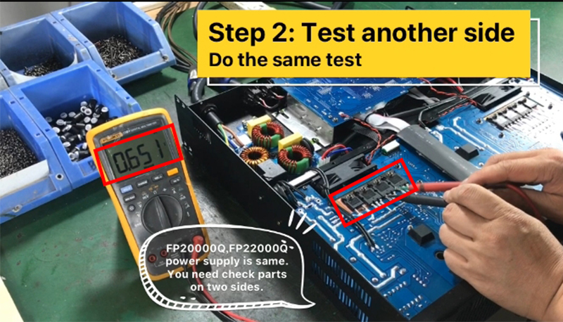
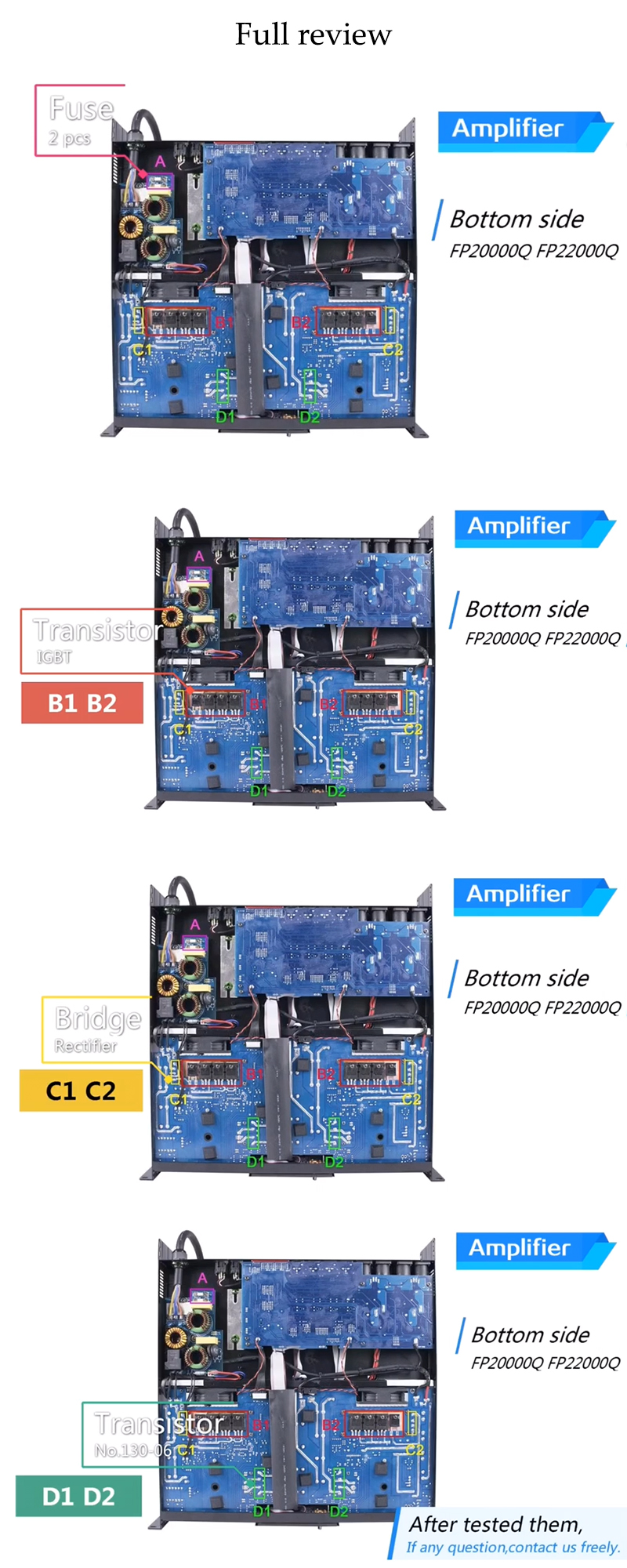
The back panel of FP20000Q, FP20000Q and FP10000Q is as shown below. (The back panel of the FP20000Q and FP22000Q are the same.)
Detailed operation steps are as follows(Test FP20000Q/FP22000Q back panel.)
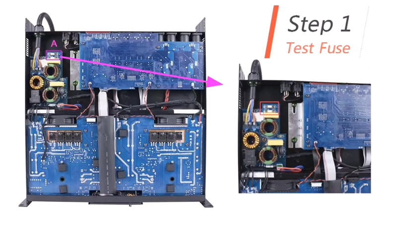
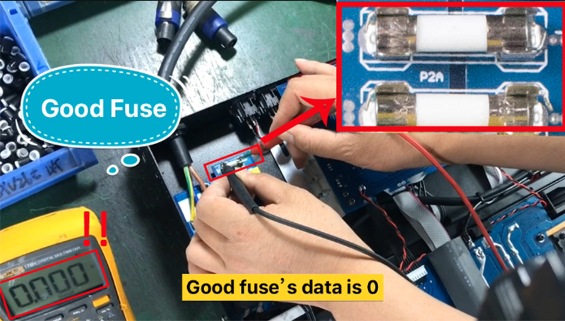
1、Step one:
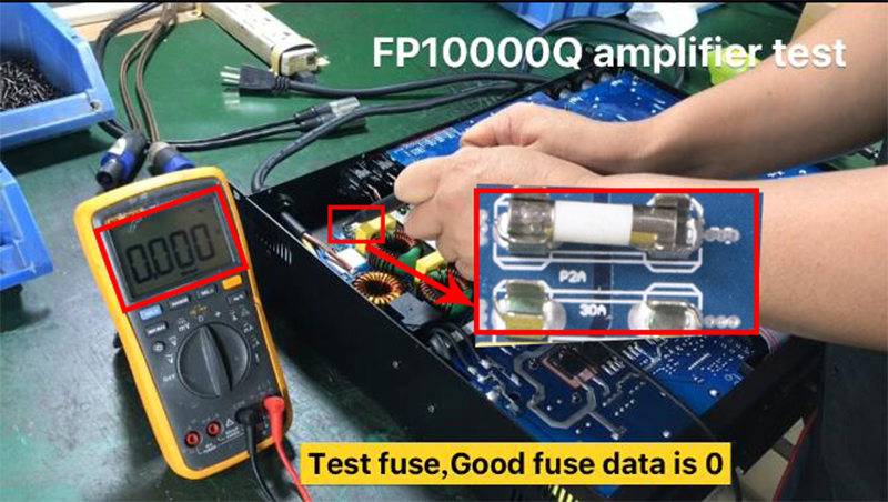
Test two fuses: Good fuse data should be showed 0.
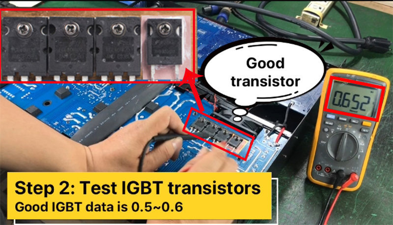
2、Step two:
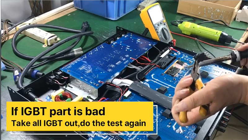
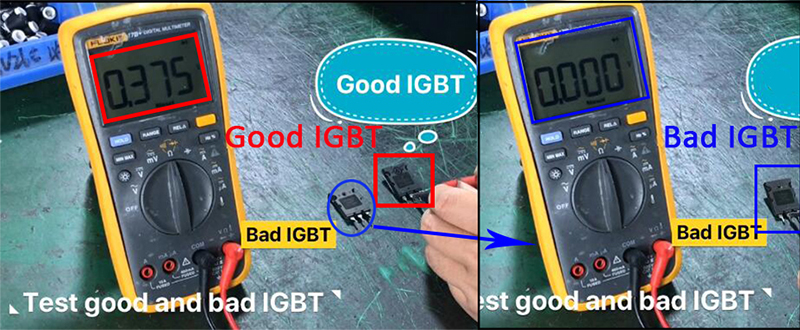
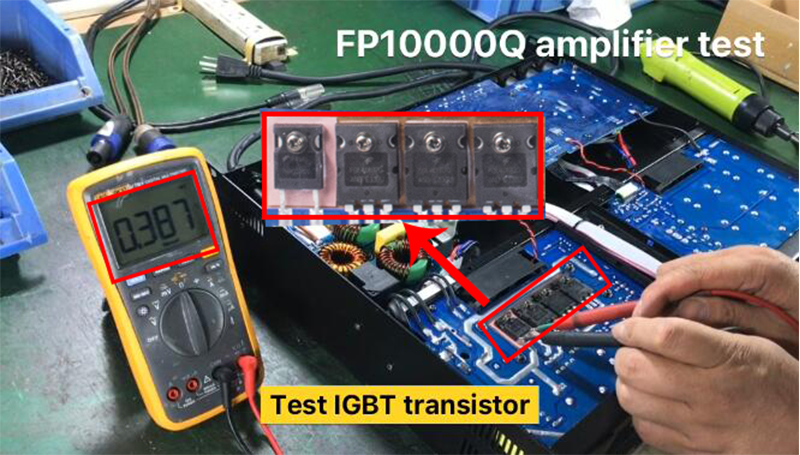
Test IGBT transistors: No.FGL40N20(6pcs),RHRG30120 (2pcs)
Normal data: 0.5~0.6
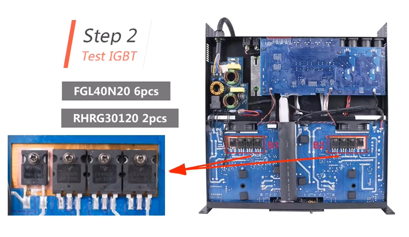
If IGBT part is bad, take all IGBT out and do the test again.
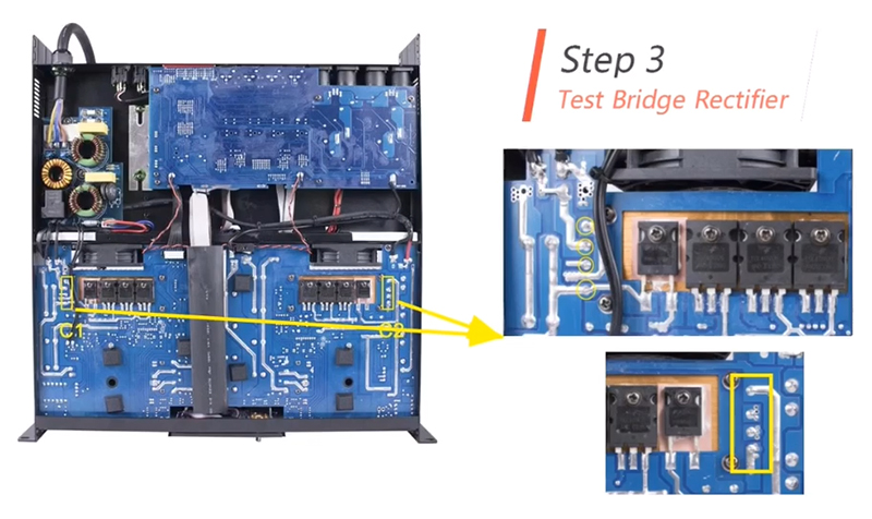
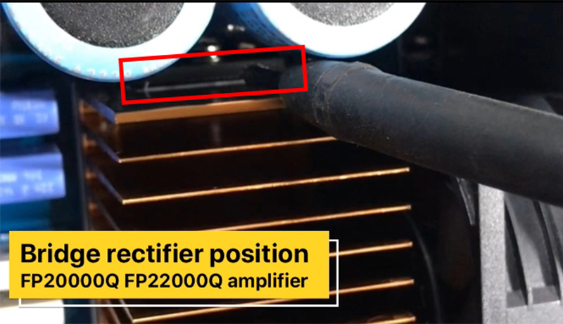
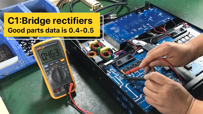
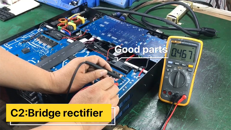
3、Step three:
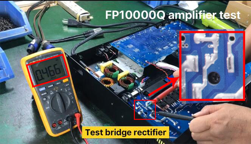
Test the bridge rectifier (2pcs)
Normal data: 0.4~0.5
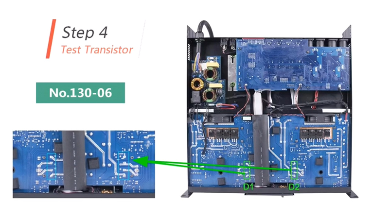
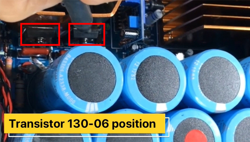
4、Step four:
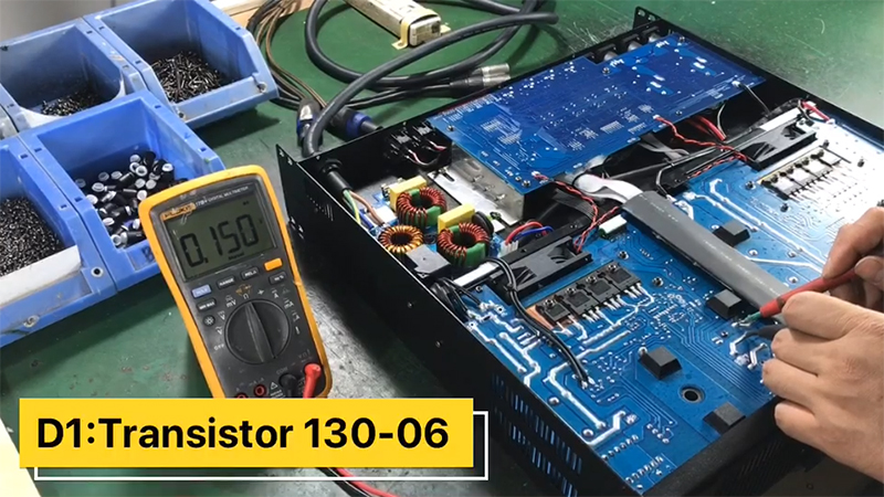
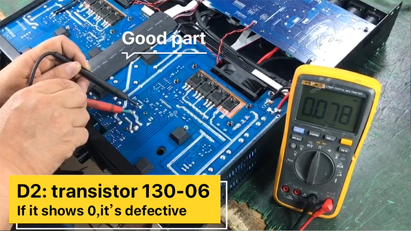
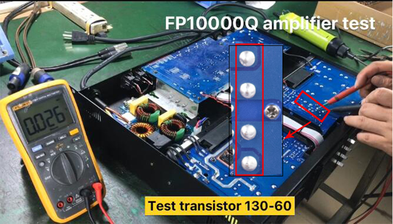
Test transistor ,No.130-06
If it shows 0, it's defective, if show any other data, it is good!
Test FP10000Q back panel, Operation is similar
| Step 1: Test Fuse Good fuse's data is 0 |
 |
| Step 2: Test IGBT transistors Good IGBT data is 0.5~0.6 |
 |
| Step 3: Test Bridge rectifiers Good parts data is 0.4~0.5 |
 |
| Step 4: Test transistor 130-06 If it shows 0, it's defective |
 |
After the detection of Fuse, IGBT transistors, and bridge rectifiers, if the three components are broken, they are replaced.
If the transistor 130-06 is broken, it means that there is a problem with the power amplifier board.
How should we protect the amplifier?
1. Connect the power amplifier to a stable voltage. Add a voltage regulator if necessary.
2. Do not use the amplifier when overloading.
Have you got it? Sinbosen hope this article can help you. If you have any quality issues, please contact us.